No AI was used for this article or assets other than for editing assistance.
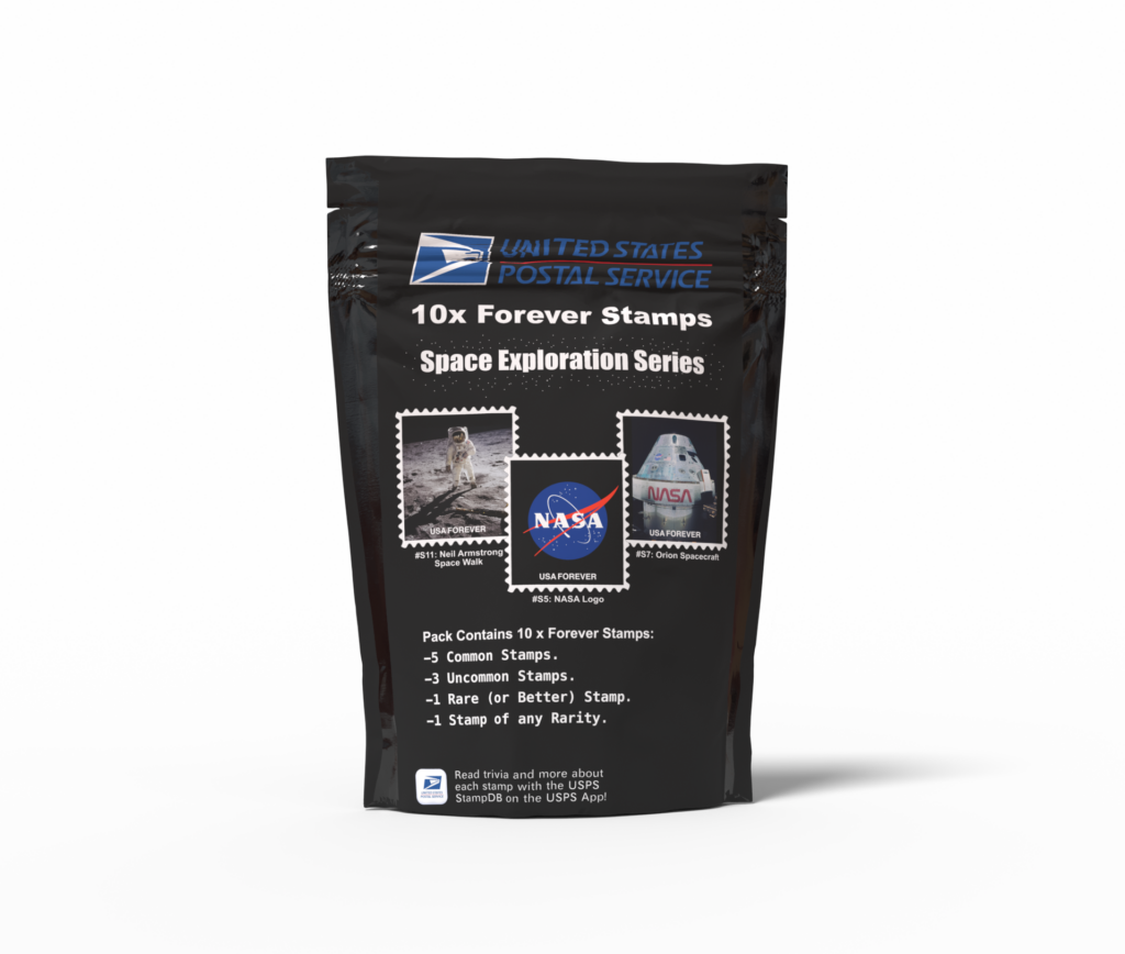
USPS Postage Stamp Blind Pack Mockup By Jake Derouin (Made with Affinity and Adobe Dimension)
The USPS is standing at the edge of a financial cliff. If changes aren’t made, the post office will run out of funds to pay its workers and deliver the mail by February 2027. Congress is currently discussing proposals on how USPS could modify its services to continue to operate. Rather than raise stamp prices or close offices, it’s time for USPS to leverage their 250-year monopoly on postage stamp issuance and cash in on the Pokémon trading card trend. The USPS needs to start selling collectible stamp blind packs!
USPS’s Struggles
Since 2007, the USPS has been operating in a steep financial deficit. Declining mail volume from the rise of digital communication and shipping competitors such as UPS and FedEx has caused the organization to fall on hard financial times. The USPS’s financial situation has become worse year after year with USPS ending its 2025 fiscal year with a net loss of $9.5 billion.
The USPS is a self-funded government agency. It is NOT funded by tax dollars. To cover its losses, the USPS is able to borrow money from the US treasury. However, the limits as to how much USPS can borrow are stipulated by congressional legislation and these limits have not been raised since 1992. In a recent House Oversight Subcommittee on Government Operations hearing, Postmaster General David Steiner testified before Congress that unless the USPS debt ceiling is raised, the USPS will not be able to fund itself by early 2027, potentially causing significant disruption in the mail service. In the same hearing Steiner not only requested the debt ceiling be raised but gave some proposed modifications to USPS’s services to cut costs. These cost-cutting measures include reducing delivery days, increasing stamp prices to nearly a dollar, closing post offices, and modifying workers’ compensation. Most significantly, the USPS is asking Congress to consider the scope of the Universal Service Mandate that requires USPS to deliver to every address in the country in order to cut costs. In response, Subcommittee Chairman Pete Sessions and other members of Congress of both parties have pushed back on these proposals, as have postal worker unions. These proposals only cut costs rather than find new revenue sources or improve existing sources. The USPS can significantly increase revenue by looking to one of its oldest services, issuing postage stamps.
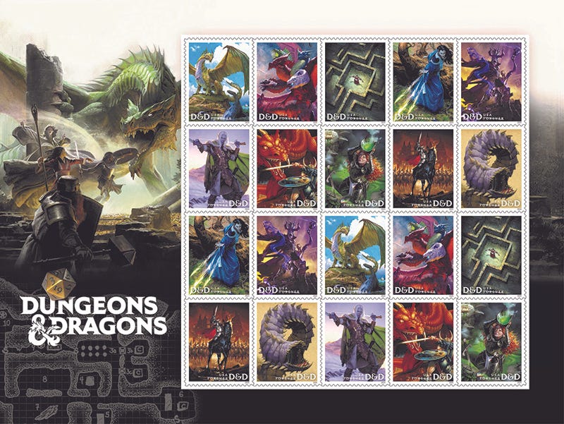
Dungeons and Dragons Forever Stamps Image Credit: USPS.com
170+ Years of Collectible Stamps
Since 1847, postage stamps have been the primary method in which postage was paid for mailing letters. Postage stamps do not expire and purchased forever stamps are guaranteed to mail a 1 oz letter even if the price of postage goes up. Postage stamps are not just a simple utility; many of them have unique designs, artwork, and messages, each showcasing a small part of American culture or history. They are essentially little pieces of government endorsed artwork. Because of this, stamp collecting has been a hobby for over a century and a half. Stamp designs have historically consisted of notable people like presidents or American heroes while other stamps feature national parks, holidays, and other commemorative statewide or countrywide events. In recent times, USPS has even partnered with popular cultural icons for stamps including Dungeons and Dragons and SpongeBob Squarepants. Despite these partnerships appealing to the younger demographic, many of those in the younger generations have never sent a physical letter and thus have never bought stamps or interacted with stamp collecting. At the same time, the younger generations clearly aren’t averse to collecting. The Pokémon trading card trend has captivated the attention and wallets of millennials and Generation Z alike.
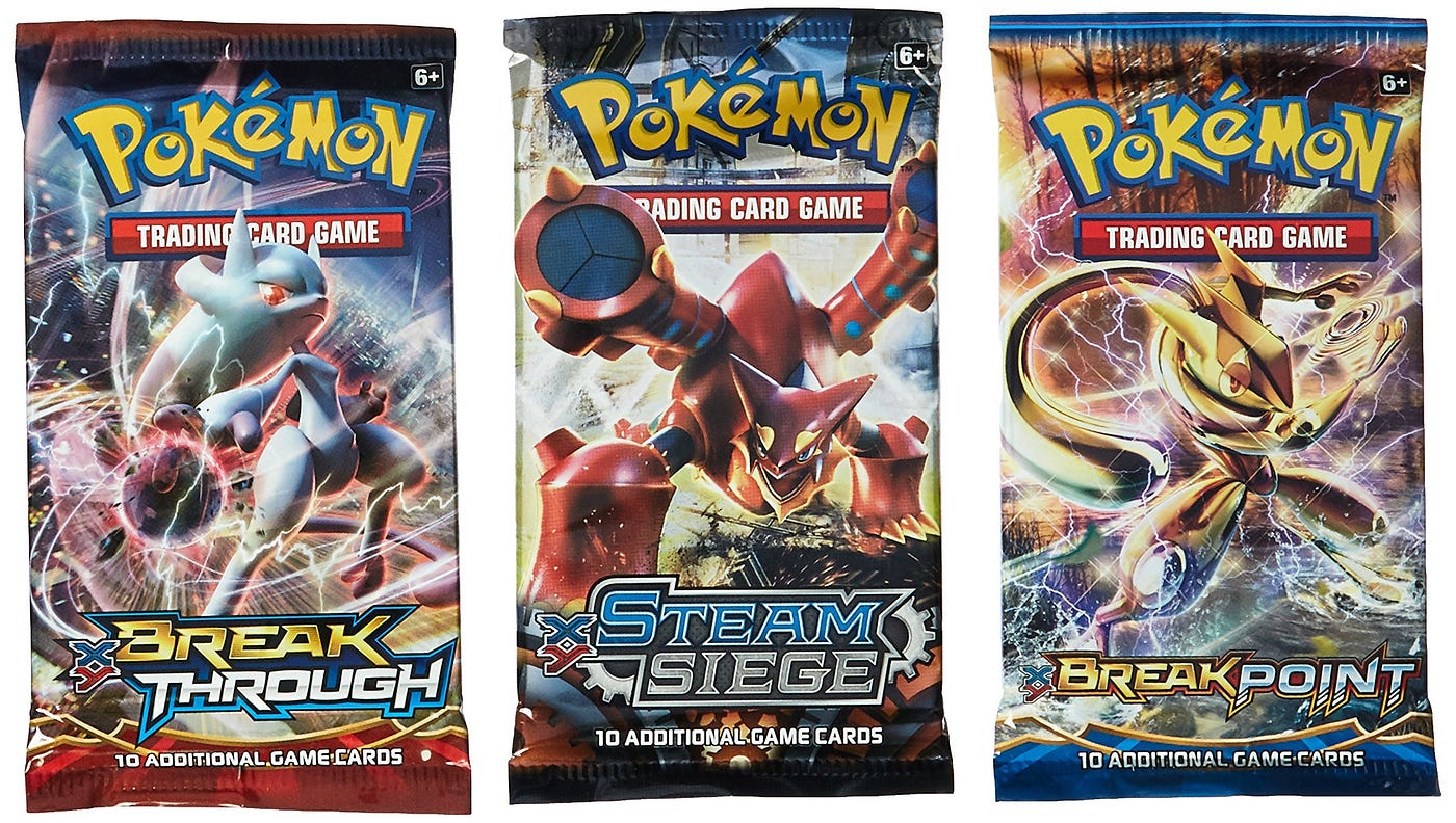
Pokémon Trading Card Game Booster Packs Image Credit: Pokémon
Gotta Buy Em All: The Pokémon Card Business Model
Trading cards have been around since the late 1800s. What started as collectible cards depicting flags, actors, and military leaders within cigarette packs has grown to include baseball players, basketball players, fictional characters and more. These cards were fun to collect but had no utility outside being collectible pieces of cardboard with art. That all changed in the 1990s with the introduction of the trading card games Magic: The Gathering and the Pokémon Trading Card Game. In Magic: The Gathering and the Pokémon TCG, no longer were trading cards just pieces of art. Instead, each card had unique mechanics that could be used within a full-fledged tabletop game that you could play with your friends. Players were now encouraged to buy cards not just for collectibility’s sake but to also try to build a unique deck and strategy to win a game. While both Magic and the Pokémon TCG are still going strong to this day, the Pokémon TCG managed to break outside the “gamer” niche and into mainstream culture, owning a 12% market share of the trading card industry, an industry now worth over 8 billion dollars.
The method the Pokémon Trading Card game uses for selling its packs is the blind pack model. Customers don’t know what cards they got until they have purchased and unwrapped the pack. Pokémon Booster card packs are by far the most popular way people buy Pokémon cards. Each Pokémon Booster pack contains 10 Pokémon cards of varying rarity. A pack typically consists of a few common cards, a couple uncommon ones, and at least one rare card with the possibility of an additional rare card or a “secret rare” card containing alternative art of an existing card. The thrill of not knowing what’s inside each pack is what keeps Pokémon TCG players and collectors coming back for more.
USPS Blind Packs
USPS could generate massive revenue if it adopts the blind pack model for stamps that Pokémon made so popular. USPS could release different themed “Forever stamp series” for these blind packs such as “Space Exploration,” “American Inventions,” or “US Highways”. Stamps within each series would be assigned different rarity tiers each with unique designs. Common stamps would be typical representations for a theme while the uncommon tier and beyond would consist of more unique or “deep cuts” from a particular theme. Rare and secret rare stamps could also consist of holographic (shiny) versions of common stamps or alternative artwork for a previous stamp design. Each blind pack would consist of 10 stamps, 5 common, 3 uncommon, 1 rare (guaranteed), 1 variable slot which has the possibility of being a secret rare stamp.
Example: Space Exploration Stamp Series
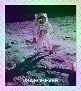
Neil Armstrong “Holographic” Stamp
Common: American Flag on the Moon, Space Shuttle Launch, International Space Station, Hubble Space Telescope, Astronaut Spacewalk.
Uncommon: Neil Armstrong Portrait, Mars Rover, Saturn V Rocket, Sally Ride, Voyager Spacecraft.
Rare: Holographic Earth from Space, Holographic Apollo 13, Golden Record, James Webb Deep Field Image, Cartoon-drawn Neil Armstrong Portrait.
Secret Rare: Anime-style Voyager Spacecraft, Holographic Moon Landing, Area 51, Roswell Incident, UFO, Global Positioning System (GPS).
As for pricing, each blind pack would cost the same amount as a sheet of 10 Forever stamps. Unlike every other trading card product, where opening a blind pack to find only common cards leaves you with worthless cardboard, USPS stamps have inherent utility built into them. Every stamp is still valid Forever postage regardless of rarity. A common and a secret rare stamp will both mail a letter, making the value proposition far stronger than traditional trading cards.
The USPS app could also add a Pokédex-like “stamp database” feature where collectors could see a database consisting of every stamp series USPS has ever released, each stamp’s rarity, and a piece of trivia about each stamp. Additionally, users could mark a stamp as obtained in the app to track their progress towards completing a set.
Financially, the USPS would benefit tremendously through breakage. With strong collectible incentives, people will buy far more stamps than they would ever use to mail. Every unused stamp would be free money for USPS to fund its operations. Many stamps would end up in binders rather than on a letter.
Perhaps a stamp collecting trend could even bring back physical letter sending. With the rise of AI making it frictionless to compose and send digital messages, a well-written physical letter carries more weight than it has in decades. Picking out a specific stamp for a specific person, writing something by hand, and mailing it signals effort in a way that a text or email never will.
The clock is ticking on USPS being able to fund itself before it runs out of money. Instead of cutting delivery days or closing post offices, the USPS needs to innovate and utilize its unique position as the only authority that can issue postage stamps. It’s time to bring a century-old hobby to millennials and Generation Z using the proven mechanics of the Pokémon Trading Card Game.
How Can We Get This Done?
Since USPS is a government organization, Congress has significant influence on how they do business. Reaching out to both USPS and your congressional representatives is critical for getting those with actual power within the organization to have their eyes on this proposal. If you contact your representatives, feel free to link this article.
Writing to the USPS Citizens’ Stamp Advisory Committee
The Citizens’ Stamp Advisory Committee is the USPS body overseeing the development of USPS stamps. They accept only physically written letters for suggestions. Their mailing address is:
Stamp Development Attn: Citizens’ Stamp Advisory Committee 475 L’Enfant Plaza SW, Room 3300 Washington, DC 20260–3501
Jake Derouin is a semi-professional triathlete with a BS in Creative Technology and Design from CU Boulder. Jake ran Division I Cross Country and Track at CU Boulder 2020–2024 and has a background in iOS mobile app development and iOS security research.
For one of my Master’s of Organizational Leadership courses, we were tasked with evaluating our groups performance as a team.
Evaluating the chat
During the course, we discussed using different methods and metrics to evaluate how well a team is working together. We were also tasked with creating our own set of team evaluation criteria to self evaluate our group. At the beginning of the class we established group communication expectations. One of those expectations was responding to each other’s queries within 48 hours. Because of this, I thought it would be an interesting experiment to create a program to analyze our groups compliance with our established 48 hour norm and have a Large Language Model (LLM) analyze our groups’ collaboration. Because most of our team interaction took place on a Microsoft Team’s chat, I decided to use the Team’s chat log as the content that would be used to evaluate our group.
Extracting the chat and metadata
The most difficult part of this task was actually getting the Team’s chat log into a ChatMessage object format that I could analyze. Microsoft Teams typically only allows an organization admin to export chat logs. To get around this, I developed a macOS app that could take in screenshots of our chat and use Optical Character Recognition (OCR) to extract the text content with high accuracy. Once the text was extracted, I looked for patterns in the extracted text to identify what parts were the message’s content, the date and time of the message, the message’s author, whether an individual was mentioned and whether or not the author was replying to another user. The function I wrote to analyze the extracted String for this information was extremely complex but in the end I was able to extract the metadata from each chat message and put it into a better form for further analysis.
Analyzing the Chat
Now that I had the chat in a format I could work with. I wrote code to determine how many messages were sent by each group member, the average response time between a chat member being mentioned and their next message (a response), and how many times they failed to respond within our group’s established communication expectation of 48 hours. This seemed to work quite well and after manually review, the accuracy of the app determining whether someone failed to respond in 48 hours was quite high.
When it came to analyzing the chat with an LLM. I utilized LLAMA 3, an open-source LLM created by Meta running on a MacBook Pro through Ollama. At first, I realized that the LLM had trouble with keeping up with the contest and learned that their was a ceiling for the amount of tokens (sort of like words) the LLM could accept at once and not lose track of context. To get around this, I ended up feeding the LLM each person’s chat history one at a time and was able to get summaries for each of their contributions. However, I was unable to get summaries of their interactions with others within the chat context as providing everything at once was not possible with this LLM.
Conclusion
This experiment was very unique and is definitely worth revisiting in the future especially as Large Language Models continue to improve.
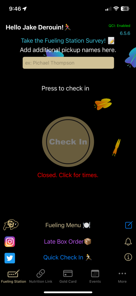
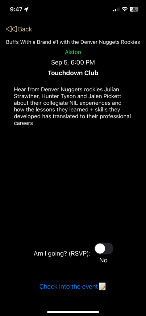
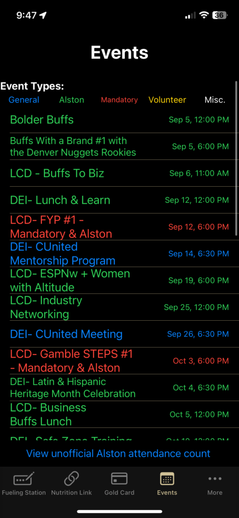
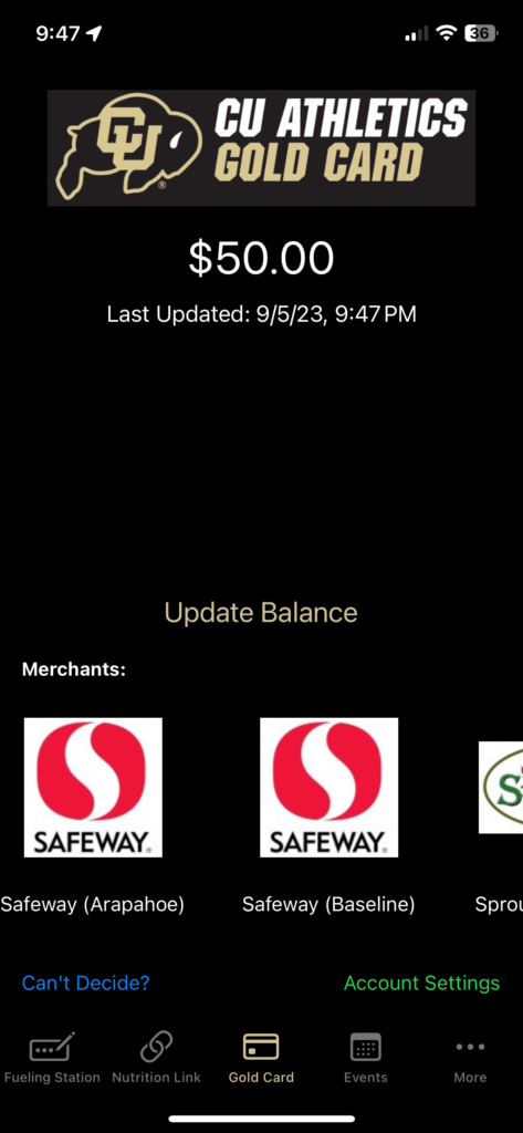
The CU Athlete app allows for Colorado NCAA Athletes to easily log their fueling station attendance, check their Gold Card balances, RSVP and check in to department events and more! The app is used by every single Colorado student-athlete on every team daily.
-Check in for meals with one button press. -RSVP for athletic department events with a single button press. -Check into athletic department events using a rotating QR code resistant to spoofing (or sharing with friends). -See their Gold Card (Flatiron Meal Plan) balance. -Play a Ralphie run mini minigame. -See the Fueling Station meal times. -Receive announcements. -Set a personal CU branded countdown widget for their events. -Reliable even in situations with unstable or no internet.
Core Features: Staff
The CU Athlete Admin iPad app allowed staff to do the following:
-Create accounts for athletes (including via importing spreadsheets). -See Fueling Station checkins in real-time and export data to spreadsheets. -Allows staff to scan athlete’s QR codes for checking into events. -Schedule athletic department events and see RSVP’s and checkins (and export those to spreadsheets). -Set the meal times for the fueling station.
The Christmas Trivia TV app was created by me in 2019 and has been updated on an annual basis. The app is an automatic trivia game that cycles through trivia questions relating to Christmas with beautiful backgrounds to go along with. The app is designed for iPad, iPhone, Apple TV, and Mac. The app is best experienced on a large TV and is perfect to throw on for Christmas parties or family gatherings.
The app utilizes a Node.js REST server I self host that has the trivia questions stored in it (students in ATLAS Web are able to query this database server for their Javascript unit).
The app also has an in-app purchase called fireplace mode that puts a virtual fireplace (a looped recording of my own fireplace) on in the background.
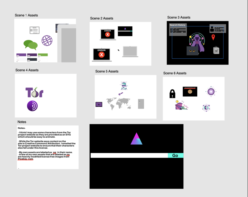
I created an educational animated video that talks about the Tor Browser. The Tor Browser is the ultimate privacy tool for browsing the internet anonymously. It also is designed to get around internet censorship of all kinds to allow anyone to exercise their freedom to access information.
I animated the video using Adobe After Effects, and edited in audio and some other enhancements using Final Cut Pro. I also created over half of the assets using Affinity Photo and Affinity Designer (Photoshop and Illustrator alternatives).
To learn more about the Tor Browser please visit The Tor Project’s website at https://www.torproject.org
Made mostly obsolete by the release of Apple Intelligence but was helpful beforehand
ML Image Sorter was an app I designed in 2024 at the request of one of my former High School art teachers. He needed a way to sort through thousands of images in Apple Photos and place them into specific albums using very unique criteria such as the style of the image.
To assist him with his request, I thought that allowing him to train his own Machine Learning models on the specific sorting criteria he desired could help him.
Writing the app
Because he works in Apple Photos and already has a very detailed photo organization strategy, I decided to make a macOS app that could take a custom Image Classification model made in CreateML, find images that match the ML model’s criteria, and copy those photos into new Photos app albums named after the model’s classification. I also made the app compatible with sorting photos into folders if he were to decide to use it outside of the Apple Photos app.
Results
The app itself worked flawlessly. However, it was limited to the performance of the Image Classification Model that the user would manually create in Apple’s CreateML application (included with Xcode). I included instructions for my former teacher on how to create an accurate model by providing good model specimen. However, since he could only include so many examples, some classifications were difficult (especially models that attempted to classify images by very obscure differences). Since my primary audience was only one person, I could have done a better job of making it more visually appealing. That said, I got the app in a good enough state to be published on the Mac App Store.
Since publishing this, the Apple Photos app received some pretty hefty upgrades in the form of natural language searching support which allows for a user to search for more specific inquires. This largely makes my software obsolete. However, at the present moment it is still available on the Mac App Store.
In 2024, after reading Edward Snowden’s book Permanent Record and utilizing Tor extensively for Project GreenWisp (due to Tor’s ability to allow me to configure local devices behind Firewalls) I found myself doing tons of research on censorship, surveillance, and the privacy tools used to circumvent both. I learned so much that I felt passionate enough to create a workshop around it and present it to students in the Blow Things Up Lab (BTU) at CU Boulder.
A simple way to get accurate votes for CU Athletic’s award show
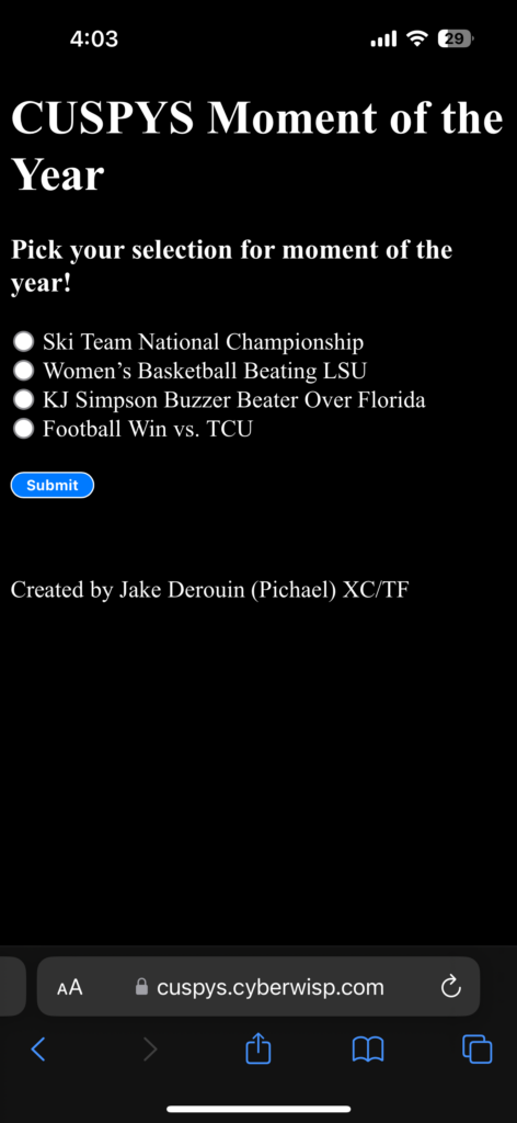
In 2024, as a president of the Student Athletic Advisory Committee (SAAC) I was in charge with organizing many aspects of the CU Sports Person of the Year Awards (CUSPYS). One of those aspects was voting for moment of the year. Moment of the year is unique in that unlike the other awards, the winner is decided by popular vote at the CUSPYS event itself rather than ahead of time. I decided I would take up creating the voting system for Moment of the year using HTML/CSS and JavaScript with a Node.js backend.
Previous Voter Fraud
Previously, there were issues where athletes would vote multiple times for the winner. At other times, the voting system was set up in a way that made it difficult for athletes to vote due to a login.
My solution: Security through feigning obliviousness
While designing the system I needed a way to ensure that athletes could not vote twice while at the same time keeping it easy to vote. I did not want to make a login as it would have taken up too much time for athletes to login and they may not know credentials. Instead, I tracked voting records through using browser cookies on the user’s device. When a user would vote a cookie would be saved on their device that they had already voted. This would make it so that the server would know if a user submitting the form had already voted.
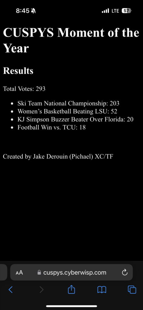
However, the cookie technique has a problem. A user can simply open up a private browser tab or clear their cookies to vote again. So I came up with an idea: What if I gave no indication that I was keeping track of who voted? To do this, I intentionally made it so that the submission success page gave no indication as to whether or not a person was voting their first time or their 15th time. From an individual wishing to vote multiple time’s perspective, it would look like voting multiple times would be as simple as resubmitting the form over and over again despite only their first vote being recorded on the server. In a sense, I was feigning not being aware of a potential security design flaw to encourage attackers to attack in a way that I did indeed secure as opposed to using other methods.
Wrap up
In the end, the method I picked to secure the voting system worked seemingly flawlessly. We were able to see the winner of the Moment of the Year being the Ski Team winning the National Championships!
A music app I made with a friend in less than 6 hours.
TuneScore is an educational app that allows a user to play displayed notes using an instrument and see if they were correct with what they played. The app utilizes the Tuna library to be able to determine what note is being played based on microphone input.
Working with a friend
This project was a class project for my friend Joelle McDonald. She enlisted my help due to my previous experience with iOS development. She laid out the requirements for the app as well as the designs for the iconography and other assets while I wrote the logic in Swift while using SwiftUI for the layout engine.
TuneScore supports a variety of different instruments and allows users to adjust whether they want to see questions with flat or sharp notes. They can also customize whether to see questions with the treble or bass clef and the max number of ledger lines a question can display.
Potential Future Features
If I were to add features going forward to this app I would consider adding the following:
The ability for the device to play the correct note.
A higher or lower feedback system to help the user.
How to play a particular note on a specific instrument.
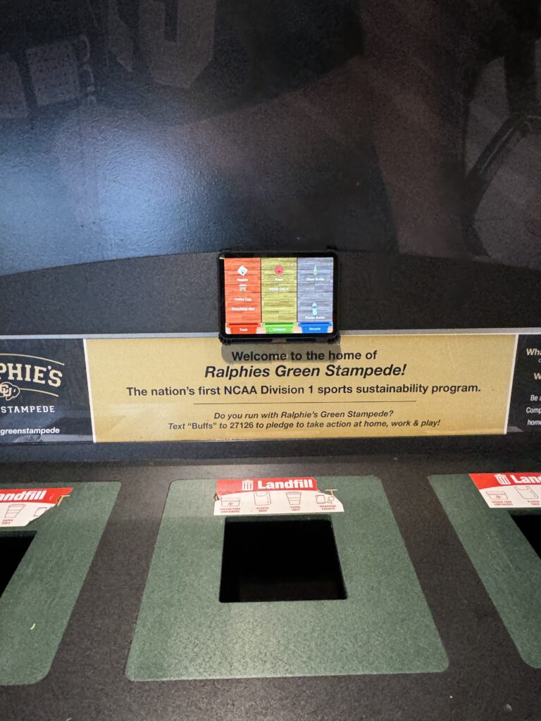
Project GreenWisp is an easy to use affordable digital waste assistant iPad app designed for high traffic waste stations. GreenWisp aims to reduce recycling and compost contamination through the use colorful animated waste characters and modern object detection technologies.
Background
Boulder County’s recycling guide
In late 2022, I learned that CU was eliminating non-food compost from their waste systems. The reason for this was a change in policy from A1 Organics, a major local compost processor for the Boulder area. This was due to high contamination rates of compost waste. Having learned this and knowing that I myself struggle to know what goes in compost, trash and recycling bins, I thought it would be an interesting experiment to utilize machine learning technologies to potentially create a system that could tell a user where items go.
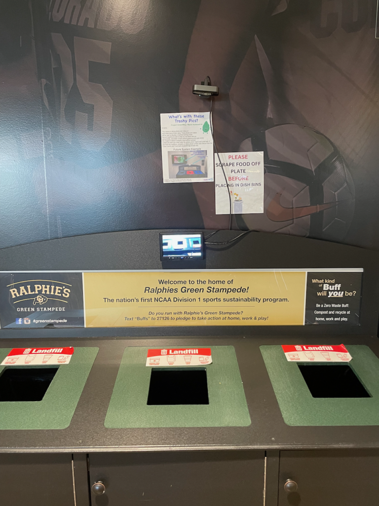
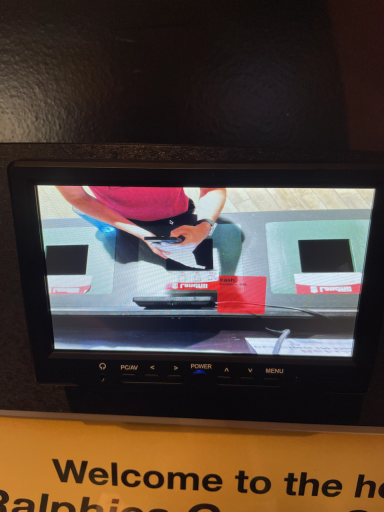
During Spring of 2023, I pursued an independent study to learn about machine learning technologies for this task with a focus on object detection. Over the course of the semester, I attached a camera and a computer to a high traffic waste station found in the athletic department dining hall. I had the camera take photos of waste items as people were disposing of them via motion detection. I collected upwards of 800,000 photos and practiced using tools such as TensorfFow and more. With these photos, I took a few hundred of them and labeled objects found in the photos as either trash, compost, or recycling. I had the goal that at the end of the semester, I would attach a display to the waste station that would show classifying bounding boxes on items as they are being thrown out. As the end of the semester drew near, I was finding it very difficult to get TensorFlow to the work well enough to reach my goal so I opted to use the Apple’s CreateML API to classify 3 item categories: Trash, Food, and reusable plates. Create ML enabled me to quickly deploy a proof of concept Mac app for a few weeks at the end of the semester. Despite some bugs with coordinate drawing on the small monitor I used, reception was good although I noticed quite a few issues.
Issues from the proof of concept
The ML model identifying a napkin as trash (the coordinate system had some issues which is why it is not aligned properly)
One of the main problems with my approach was that training a model to identify waste categories would only allow me to use that model at one particular location. Items that are recyclable or composable in one location may actually contaminate those same bins in other locations and should be thrown in the landfill instead. Another issue was that given my limited labeling resources, labeling thousands of items to produce a highly accurate machine learning model given that waste items are frequently of different sizes, shapes and colors was not feasible. If I couldn’t make an accurate model for a system that relies entirely on ML, I wouldn’t be able to help reduce contamination.
Fast forward to Fall of 2023
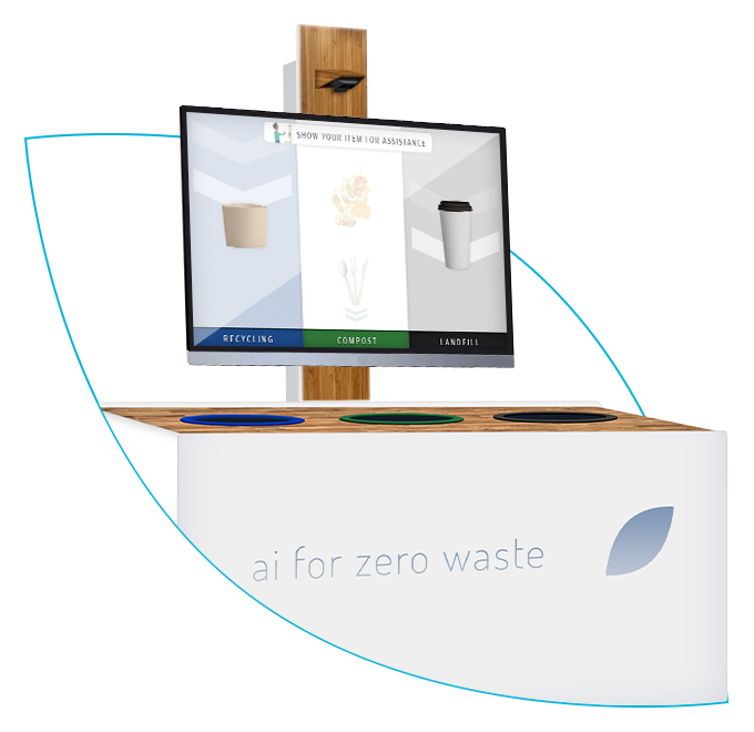
One of our precedents: The Oscar Sort AI waste bin
Having identified some flaws with my previous approach towards this idea, I brainstormed a new approach that addresses these concerns. During our precedent research phase of the capstone process, I found that earlier in 2023 a product was launched called Oscar Sort. This product had a similar setup to what I had previously envisioned that used machine learning to identify waste objects. Another precedent I found was the EvoBin. This system did not use artificial intelligence at all but rather was a screen designed to be placed above waste stations that cycled through a prerecorded video with images of specific items to that location and which bin they belong in. The EvoBin would also occasionally show trivia or fun facts to keep users interested. When looking at these precedents what stuck out to me the most was how all of the precedents we researched required additional hardware to be installed by professionals and were very expensive with some of them costing tens of thousands of dollars. All of the precedents also seemed to use the same realistic non-animated images for displaying waste items.
Brainstorming
An example of Japanese Kawaii style characters (these two were used for the 2020 Olympic Games)
After completing the precedent research phase, I began brainstorming how I could create something that achieves something similar to the precedents I identified while doing it in a novel fashion that addresses their shortcomings. The most significant shortcoming in my opinion was the high cost of hardware found in these precedents. Having previously used Apple’s object detection technologies for my first attempt at this project last year, I thought it would be interesting to create an application that could be run entirely on an iPad. By running the app on an iPad, I could achieve similar results for a significantly lower price and with no additional hardware required. Despite the easy to use Apple CreateML suite, knowing my limited ability to label tons of data on my own for highly accurate object detection models for waste, I thought that it would be interesting to take EvoBin’s approach of creating engaging digital signage as the first priority for project but spice it up with less “industrial” style images that all of the precedents have. I have always been interested in the cute style of some Japanese animated characters such as Pokemon. This style is commonly referred to as Kawaii style and to me, I always felt like characters drawn in this style would get my attention. I thought perhaps I could incorporate that kind of character style into this project. As for the AI features, I decided that object detection of items could still be present in the project but it would take a secondary role in which select items that could be successfully identified would have an additional animation to tell the user what item they currently are holding.
My logo
What’s in the name?
The company name I use for all of my technology services is CyberWisp with the word wisp being a synonym for a ghost. My branding assets include some cute and colorful ghost like characters. Given that this project also has cute characters, I could continue the naming pattern with the name GreenWisp. Having done some additional brainstorming, I had come up with a general structure for the project and settled on 4 key goals.
4 Key goals
Design an iPad app that:
Utilizes cute kawaii style animated characters to get the attention of passerby throwing away waste to help them accurate put their waste in the correct bin.
Incorporate machine learning object detection to identify items in real time when feasible.
Allow for easy customization by waste management administrators for their specific waste station configuration.
Require no additional hardware outside of an iPad.
Getting into groups
Because I have around 5 years of iOS mobile app experience, I felt pretty confident to tackle the technology challenges on my own. However, my artistic ability to create and animate original cute looking characters that don’t look like they want to eat your soul was lacking. That’s why I sought out Ian Rowland and Nik Madhu to be in charge of creating the character animations. Both Nik and Ian had experience with Adobe After Effects and were equally passionate about the using their skills to work towards a project designed to fight climate change.
Diagrams
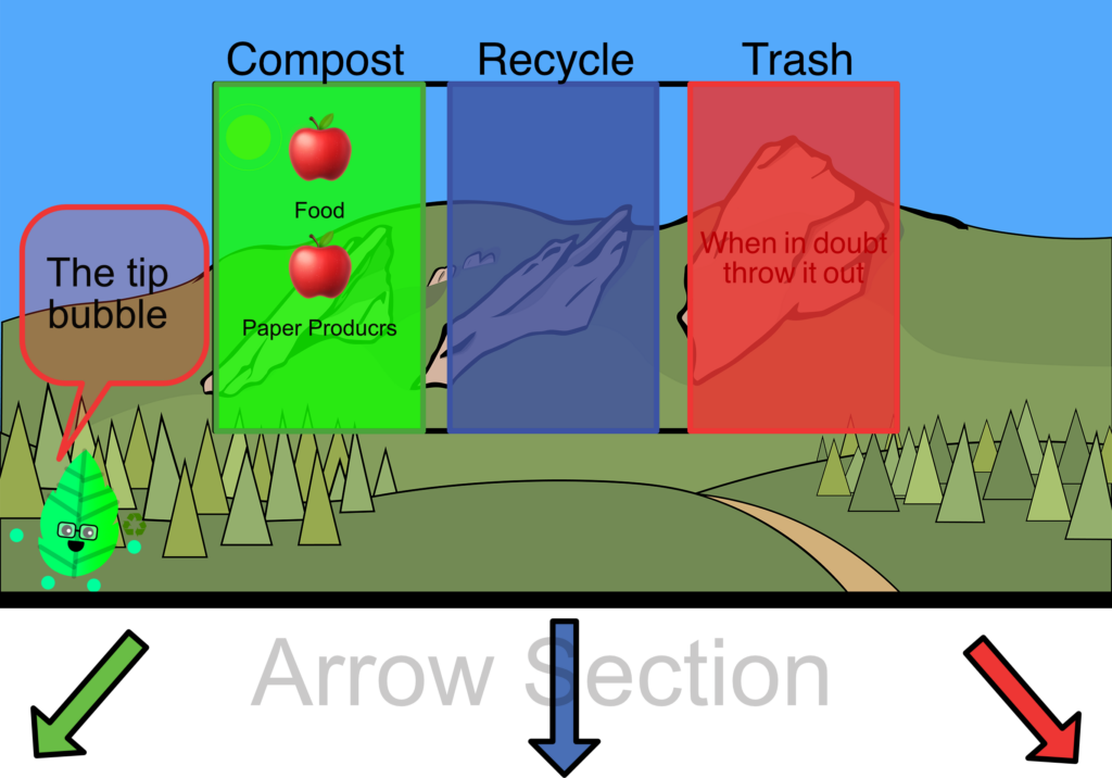
A VERY early diagram of the waste screen.
Before building an app, I usually will mock up what the app will look like that way I can start to figure out how the pieces will fit together from a user interface perspective and a coding perspective. We based the design of our sketches off of ideas from precedents such as EvoBin and Oscar Sort. We opted for a column interface where each column represented a particular waste category such as trash, compost or recycling. Since waste stations can vary by the number of categorical bins and the position of those bins, we needed to allow for easy customization. We quickly found that the screen real estate of a 10.9 inch iPad device is limited for all the information we want to display to be easily read from an arms length so every design decision had to be carefully made and some features had to be cut. One of the original ideas was incorporating Evo Bin’s trivia and other fast facts into the app but we quickly found that this would be very difficult to do because of the limited screen real estate. We decided on displaying three items at once per category and allowing up to four categories of waste to be displayed at one time. We also included arrows in our diagrams that could be customized to point in the direction of a particular bin.
Acquiring Materials
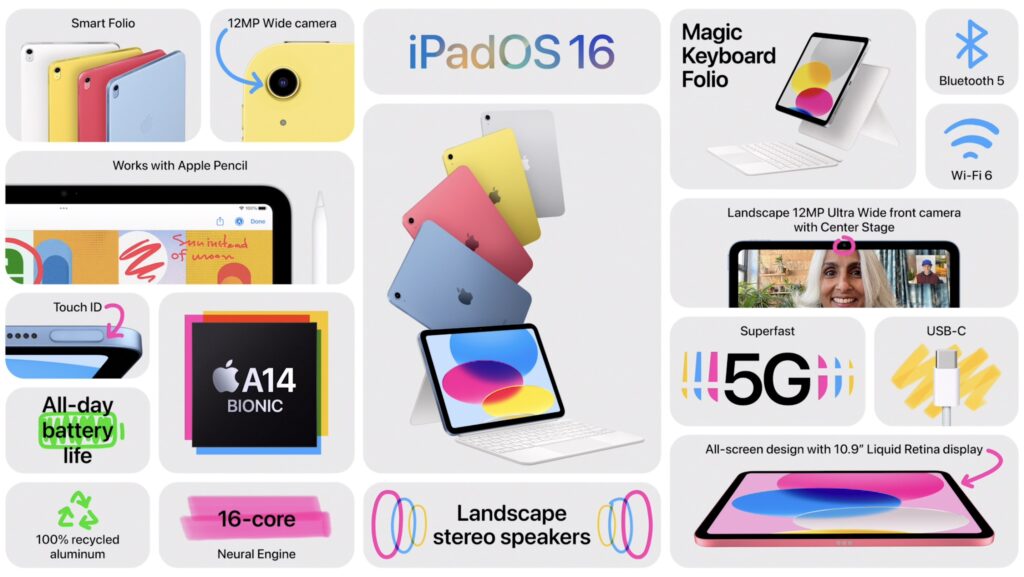
Apple”s specs for the iPad 10th generation.
Apple has numerous iPads available for sale each with different screen sizes and capabilities. Since one of my project’s focuses is affordability, I thought it would be wise to design my app targeting one of the cheaper iPads available rather than the high end iPad Pro’s. By doing this I could ensure that the app could work on as many devices as possible. After doing some research, I found that the 2nd most affordable iPad has an ultra wide angle front facing camera that could be very useful for classifying items in front of a wide waste station. I ended up purchasing a 10.9 inch iPad as well as a high speed SSD drive for moving large amounts of images when training machine learning models.
Firing up Xcode.
Since I was creating an iPad app (with the additional ability to run on macOS), all of the code was going to be written in Xcode using the Swift programming language. I also decided to use SwiftUI to create the views (which took a little bit to get used to since most of my expertise has been with working with UIKit). As a mobile app developer, one of my first tasks when starting a new app is establishing how the app’s data will be structured and accessed so I don’t have to rewrite and rethink large amounts of logic later.
Structuring the data
When structuring the data, I concluded that the waste columns were by far the most important data structure in the app. Each column would represent a particular waste category such as trash compost or recycling. Waste admins can name these columns from the configuration menu as well as set the background color. Most importantly, items can be assigned to each column. Since I was going to be working with animations, each column object would also manage a SpriteKit view (or SKView) to control animations.
For saving the data, I figured I would use a single JSON file that would be loaded whenever the app starts.
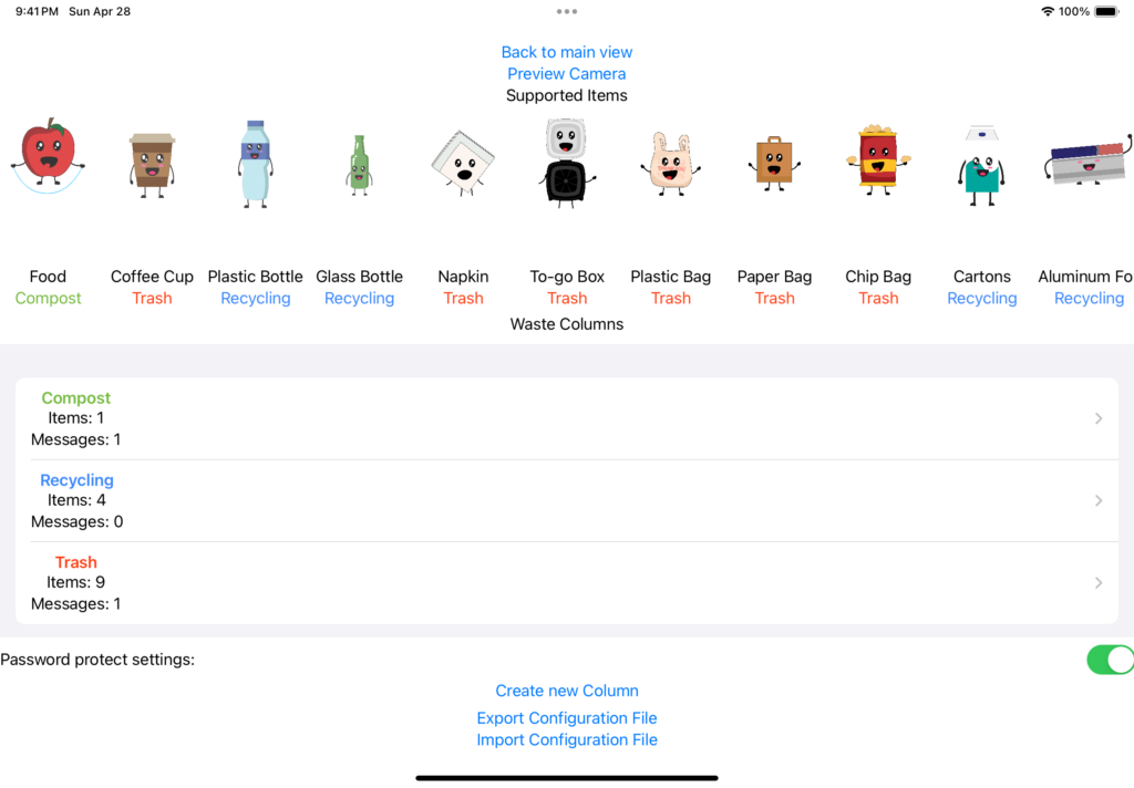
Starting the UI: Configuration Screen
Before I could work on the UI that would display items, I had to build a method of creating waste categories and assigning items to those categories. I decided to do this by designing the settings screen first. The settings screen shows all of the waste items that are available to categorize and allows you to create a waste column, customize the color, name and which items belong to that particular category. I used quite a few SwiftUI lists to allow easy selection of data. The configuration screen would be accessed by a simple tap from the main screen.
Displaying items
Now that the configuration screen was complete, my next task was displaying items on the screen. Because we were limited in screen size, I thought it would make sense to show only 3 items at once per category. Items would be displayed with their animation (or a static image at this point in time) as well as a label of what the item is below it. Categories with more than 3 items would rotate out items out every 5 seconds by fading the items. I was able to achieve this by creating “waste groups”, essentially groups would reference up to 3 items in a category and would be able to rotate through them. This would also allow me to force a particular waste group to appear at any time which would be needed later for object detection.
Dropping the arrows and the animated backgrounds
The old arrows and backgrounds.
While my primary job in this project was working on more of the technical pieces and UI, I did have to make some aesthetic design decisions. Originally I thought it would be useful to have arrows present in the app that could be set to a specific direction referencing the position of the actual waste station. Over time, I found that the arrows were taking up too much screen space so I decided to remove them. In place of the arrows, I added in waste bin images that would take a fraction of the space at the bottom of the screen (and looked significantly better). Additionally, I had placed an animated SpriteKit background effect for every column that was a bit distracting. I ended up replacing those animations with a wooden texture and coloring that according to the user’s specified column color.
Adding in animations
A screen recording of the animations added.
Now that Ian and Nik had some animations complete, I needed to add them into the app. Because each category has a background color, I could not simply loop a video of each character’s animation as .mp4, .mov and other video formats don’t support transparency. Instead, I exported a sequence of png images from each character’s After Effects file and added them into Xcode to be loaded as a Sprite’s texture atlas.
Object Detection
A photo taken and labeled using RectLabel Pro of a Coffee Cup to train an object detection model.
One of the main goals of this project was to add waste item recognition capabilities using object detection. At this point in time, the app was able to successfully cycle through animations of items but had no object detection features yet. Since we were planning on doing our user testing in the CU Boulder Athletic’s dining hall, I thought I would target two common contaminant items from the Fueling Stations: black togo containers and Ozo coffee cups. To get the machine learning model working I took around 150 photos of these two items in different positions. Because the iPad was going to be mounted on the Fueling Station waste station, I put the iPad up on the waste bin to take the photos. I used an automatic photo taker app to take the photos in quick succession with a 3 seconds delay in between each photo for me to rotate the item into a unique position. I then labeled them with RectLabel by drawing bounding boxes on these images.
The CreateML training program.The model classifying a never before seen image.
The process of labeling images is very tedious and took a couple of hours as I wanted to ensure that the bounding boxes were tight around the items to ensure the greatest accuracy. After labeling them, I imported the images into CreateML and my computer whirled up its fans to train the object detection model. The resulting model seemed to have good accuracy according to CreateML.
Incorporating the ML model into the app
Video of the object detection animation.
Now that I had a trained model file, I needed to get the model to work in the app. For IOS platforms, using camera features generally requires you to use AVFoundation. This is one of the most confusing frameworks that I have worked with on iOS. Luckily, Apple had an example app called Breakfast Finder available that could identify certain foods via object detection. I was able to repurpose some of Breakfast finder’s code and attempt to figure out how it works. After a bit of trail and error, I successfully got the debug console to print the detection inferences. Interestingly, unless you set the confidence level up a bit, the console will repeatedly spam random detections. This single variable was something that I would need to play around with.
Getting the console to print detections was nice but I needed something to happen on the characters when the item the character represents was detected that the user would be able to see. I decided an easy animation to do would be to have the characters grow and shrink in size repeatedly when an item was detected. To achieve this, I had the app look for items via the ultra wide camera and then if one is detected, determine which waste column it belonged in and then force that column to show that item on the screen and trigger the animation for a minimum 0.5 seconds with the animation looping if that item remains detected.
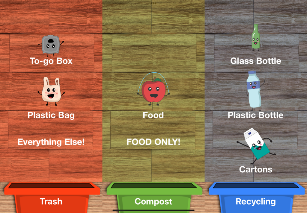
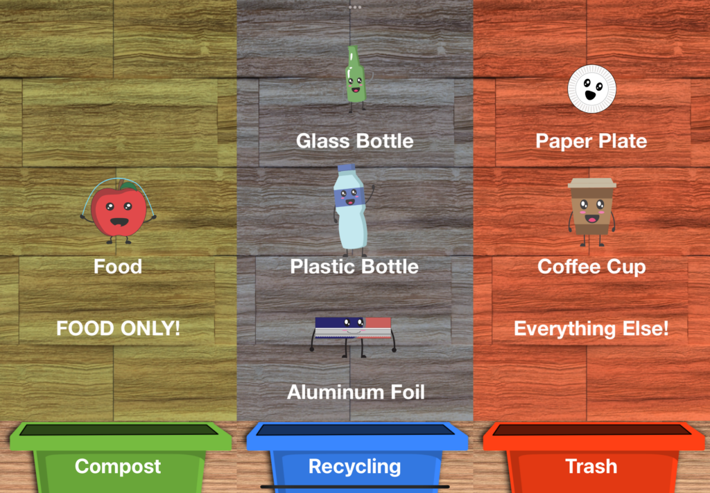
Waste Messages
Two persistent waste messages displayed. FOOD ONLY and Everything Else!
While my goal was to include a large swath of items to display, I realized that I might not be able to animate every item. Additionally, some users might just be in such a big rush that they don’t have time to look at the items that belong in each bin. To attempt to solve these two issues, I added customizable labels to the app. These labels would be created by a waste admin and had two modes: persistent, or rotating. In persistent mode, these labels would always be displayed on the screen in place of one of the animated items. Waste admin’s can set the position of the persistent labels to be on the top of the screen middle or bottom. Persistent labels are useful for messages such as “TRASH ONLY” or “NO FOOD” In rotation mode, the labels act like items just without an image. The labels will rotate as if they were another item.
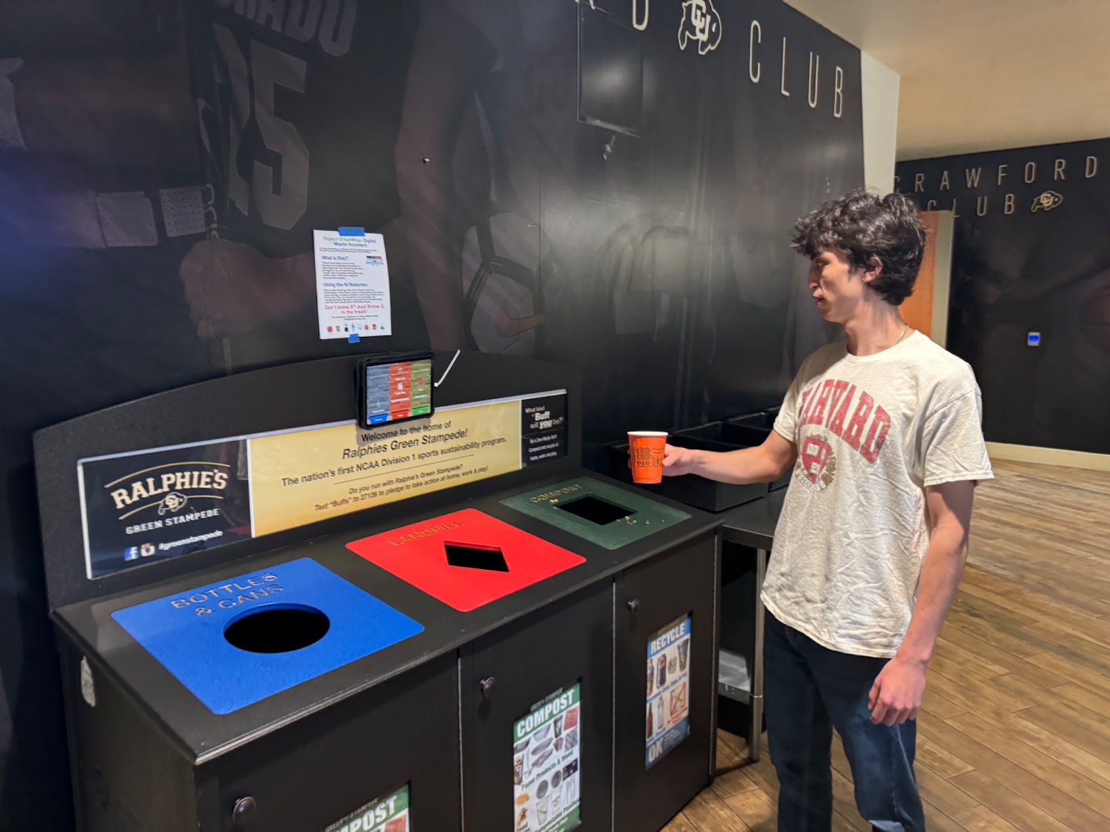
Deploying a demo into the athletic department
The demo setup in the athletic department.
During our capstone class, we had to do multiple forms of user testing. For one of our user tests, we decided to observe athletes in the athletic department interacting with the GreenWisp system and gather feedback from observations or interviewing athletes directly. Over spring break I set up the iPad on a waste station in the athletic department. I achieved this by using some industrial Velcro, and running an extension cord from the nearest outlet to the iPad.
After setting up the system, we briefly interviewed athletes in the fueling station about their experiences. We interviewed some who were at their tables, some just before throwing items away, and others just after throwing items away. We received the following testimonials:
Some individuals used another waste bin and did not interact with the system.
Most individuals thought that the characters were cute and not uncanny.
Most individuals said that they have looked at the system for help in sorting their waste at least once in the past week.
A few individuals said they successfully had their items identified by the system.
Feedback of the system was positive.
Other things we took away from this experience:
Users liked the character designs
We could improve our ability to get user’s attention potentially through identifying when they walk up.
The object detection works but is a bit limited due to only supporting 4 items currently.
We could improve the animation when an item is detected so that it can get the users attention better.
Users only spend a small amount of time at the waste bin even when interacting with the system.
Some users don’t know about the ability for the iPad to detect items. We should potentially communicate that better.
Import and exporting configuration
The configuration JSON.
With the focus on adding additional customization options to the app, it became obvious that someone configuring the system might want an easy way to copy their preferences over to another iPad running GreenWisp. Because I had previously setup everything to be saved as one giant JSON file, it was super easy to add the ability to import and export the configuration to send to another device. I initially considered doing this via a QR code, but unfortunately, the JSON files were way too large. In the future, I could potentially use a QR code by having the device upload the configuration to a server and then giving a generated link as a QR code for devices to download that user’s configuration.
Fixing the RAM issue
Xcode’s Debug Inspector RAM page.
As Ian and Nik continued to push out expressive animations of different waste characters for me to add to the app, I eventually ran into an issue with the app started to crash within a few seconds after launch. I quickly determined that this was an issue relating to running out of memory on the iPads. The iPad we were using has a ram limit of around 4 GB and we were quickly exceeding that threshold due to having so many high-quality animations present in the app. I tried a few methods to fix this, one of which involved offloading all of the SpriteKit animation frames whenever an item was rotated out from being displayed. This fixed the ram issue but caused animations to be extremely choppy and lots of frames to drop. I realized that I needed to make the file size of each items png animation frame smaller. So I went back into adobe after effects and re-exported every single item with a lower quality on the PNG sequence images. This process took some time, but eventually I was able to significantly reduce the amount of ram used without dropping frames.
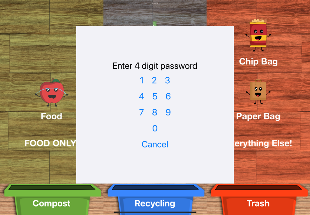
Password locking the configuration page.
After deploying a demo into the athletic department, I would occasionally come to a meal to see that the app was stuck on the settings page due to someone attempting to interact with the iPad via touch. I needed a way to prevent non waste admins from accidentally opening this page and changing settings. I added in a password lock feature. Waste admin can optionally lock the configuration screen with a password that they can set. When a password is set, tapping the screen, when it is showing waste items will display a password prompt. If no action is taken within 15 seconds the prompt will disappear.
Final tweaks
Towards the end of the semester, I worked on adding additional items for waste classification. I was able to train a model that could now successfully identify chip bags and cartons in addition to the previous togo container and coffee cup. I also continued to add in new character animations as Nik and Ian completed them.
What’s Next
As the semester concludes I plan to continue this project in the future. I aim to release this app on the App Store within the next few months. Before releasing I still need to:
Fix some occasional crashes
Add in the ability to switch cameras
Add in a camera preview feature for seeing what the camera sees for waste identification.
Allow for enabling and disabling object detection features for specific items.
Have an additional animation or state change when the device detects an approaching person.